click
laminate
SCOPE
Most people are familiar with click laminate floors and may have installed them in their homes at some point. Laminate floors are composed of multiple layers of synthetic materials, with the innermost layer typically consisting of resin and fiberboard materials fused together through a lamination process. These floors are relatively easy to install for DIY enthusiasts and are supplied in the form of tongue-and-groove planks that can be easily clicked together.
Next to the obvious benefits, such as easy installation, cost-effectiveness, and easier maintenance compared to more traditional flooring, there are also some disadvantages. The quality of the floor is influenced by the design of the click connection and the dexterity of the user, which can result in issues like raised edges and unevenness. Mishandling during the interlocking of panels can easily lead to damage to the edges of the laminate. Furthermore, under normal use, damage due to point loads can occur more quickly at the joints than with traditional flooring.
The challenge, therefore, is to create a click connection that allows for easy installation without damage while also being robust enough to withstand daily use effectively.
APPROACH
The finite element simulations of these click connections is non-trivial due to the contact between the components and the significant relative displacements in which both parts slide over each other. Fortunately, thanks to the length of the floor panels, many influences can be examined using a 2D model, making it easier to optimize the meshing of the components for such contact simulations.
For this specific project, several types of laminate floors were considered, and the effect of the most relevant parameters on the connection was investigated. These parameters include:
- The nominal geometry of the connection, which can, in turn, be reduced to a number of geometric parameters such as fillet radii, angles, etc.
- The friction properties of the contacting surfaces, which can be manipulated either by surface treatment or by the addition of other materials or even separate components.
- The installation angle, i.e., how the connection is realized as the user manipulates the panels.
In this parameter study, each configuration was then scored based on:
- The force required to achieve the panel's installation (preferably as low as possible).
- The horizontal force required to separate two assembled panels (preferably as high as possible).
- The maximum stresses that occur in the connection under a vertical point load caused by a chair wheel, according to the European standard EN 425 (preferably as low as possible).
In the latter case, a 3D model is used.
RESULT
Such a parameter study provides valuable insights into which parameters are critical for the connection and are relevant for further optimization studies. Based on these results, recommendations could be formulated to modify the geometry of the connections and change the friction properties of the surfaces by adding other materials for different types of panels.

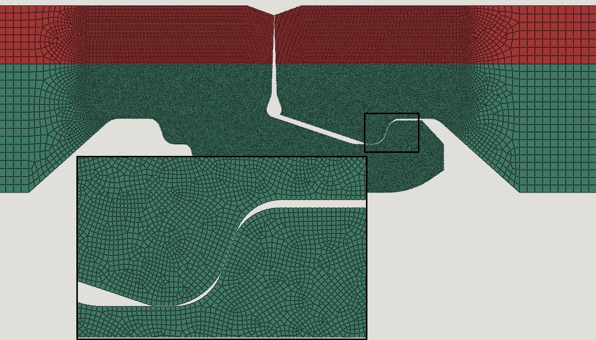
View of the optimized mesh in the contact zones of the connection
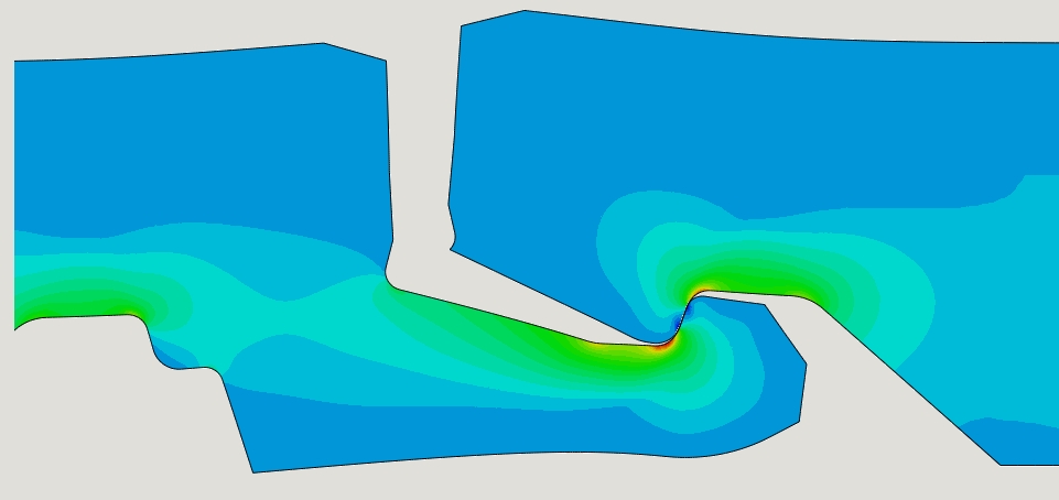
Impression of the tensile stress distribution in the connection under horizontal loading
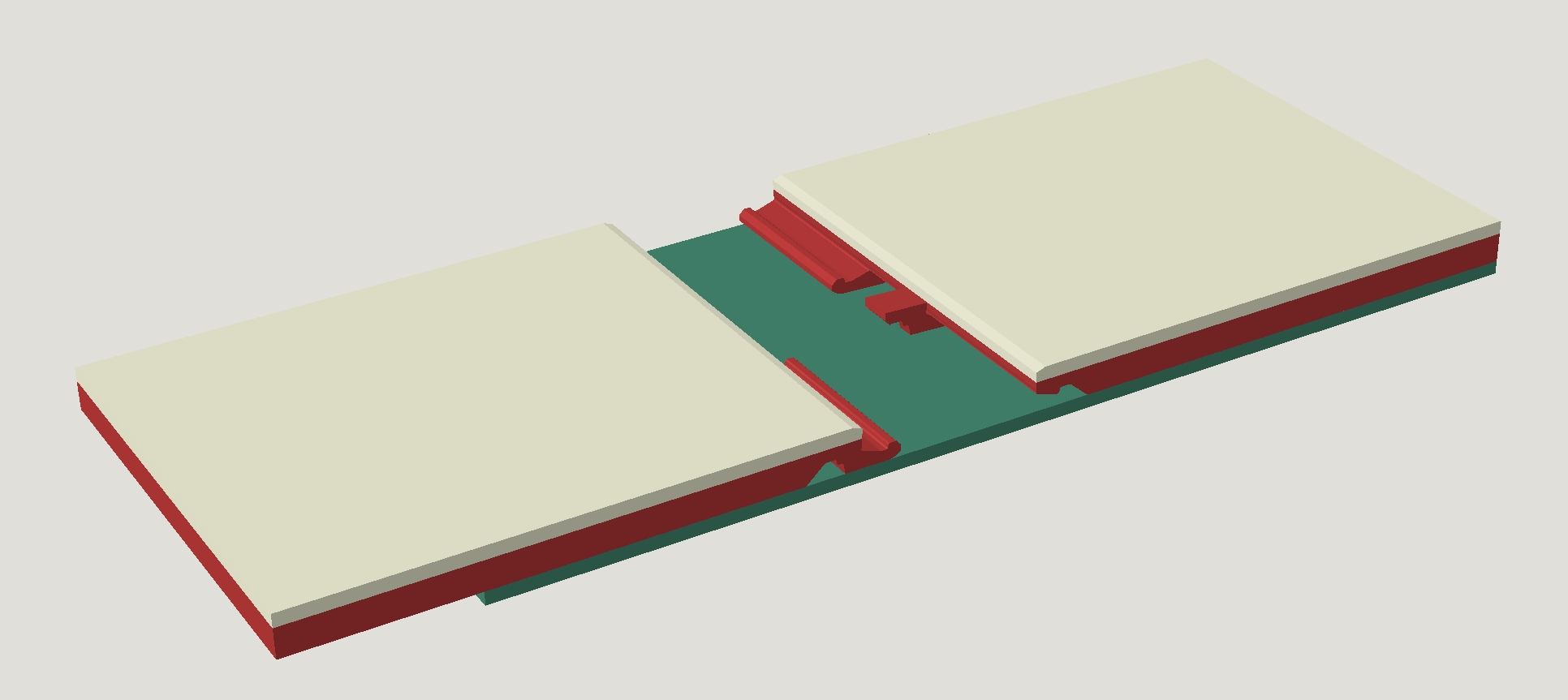
3D model geometry to account for point load calculations