vibration fatigue
during piling
operations
SCOPE
A current deflecting wall serves as a vital barrier to impede the influx of sediments into a harbor, effectively mitigating the need for extensive dredging in the future. Typically, this construction features a lower threshold that ensures the diversion of sediment-laden water away from the harbor. Simultaneously, the upper section consists of a screened structure mounted on piles, facilitating the flow of the less sediment-laden water into the harbor.
The piles, crucial components of this deflecting wall, are equipped with various welded appendages toward the top for the installation of the wall and subsequent modifications. During the pile design phase, considerations were predominantly focused on operational loads. However, complications arose during the driving operation, where the piles undergo cyclic dynamic loading as they are pushed into the ground. This dynamic loading induced vibrations in the welded attachments, leading to significant deflections and stresses that, after several hours, led to premature weld failure due to fatigue.
APPROACH
In this project, a transient dynamic analysis was conducted to pinpoint critical areas in the construction and propose necessary modifications. To streamline computational efficiency while maintaining acceptable accuracy, the 40-meter-long piles and their welded appendages were modeled as shells without explicit weld details. The dynamic simulation involved subjecting the top edge of the pile to a vertical translation with a 5 mm amplitude and a frequency of 24 Hz. The transient analysis spanned 10 seconds, during which a steady-state condition was achieved.
Despite the absence of explicit weld representations in the model, an evaluation of weld fatigue life can still be undertaken using the hot spot stress method, also known as the structural stress or geometric stress approach. This method, as outlined for example in the IIW guideline by A. Hobbacher, is now a widely adopted Finite Element Analysis (FEA) technique for determining stress concentration factors at the weld toe. It is referenced in industry standards such as Eurocode, FKM, DNV, and ASME.
By carefully selecting elements, local mesh parameters, and other considerations, stress values can be extracted from the finite element model and extrapolated using specific formulas to determine the hot spot stress near the weld toe, and, from it, the fatigue life. This procedure was performed for all welds on the pile to identify critical zones and propose modifications.
RESULT
Following the findings from the initial design, critical welds were pinpointed due to excessive vibration of specific plates in a direction perpendicular to their faces. Considering the already manufactured geometry of all piles, a strategy was devised to address this issue by incorporating reinforcement plates.
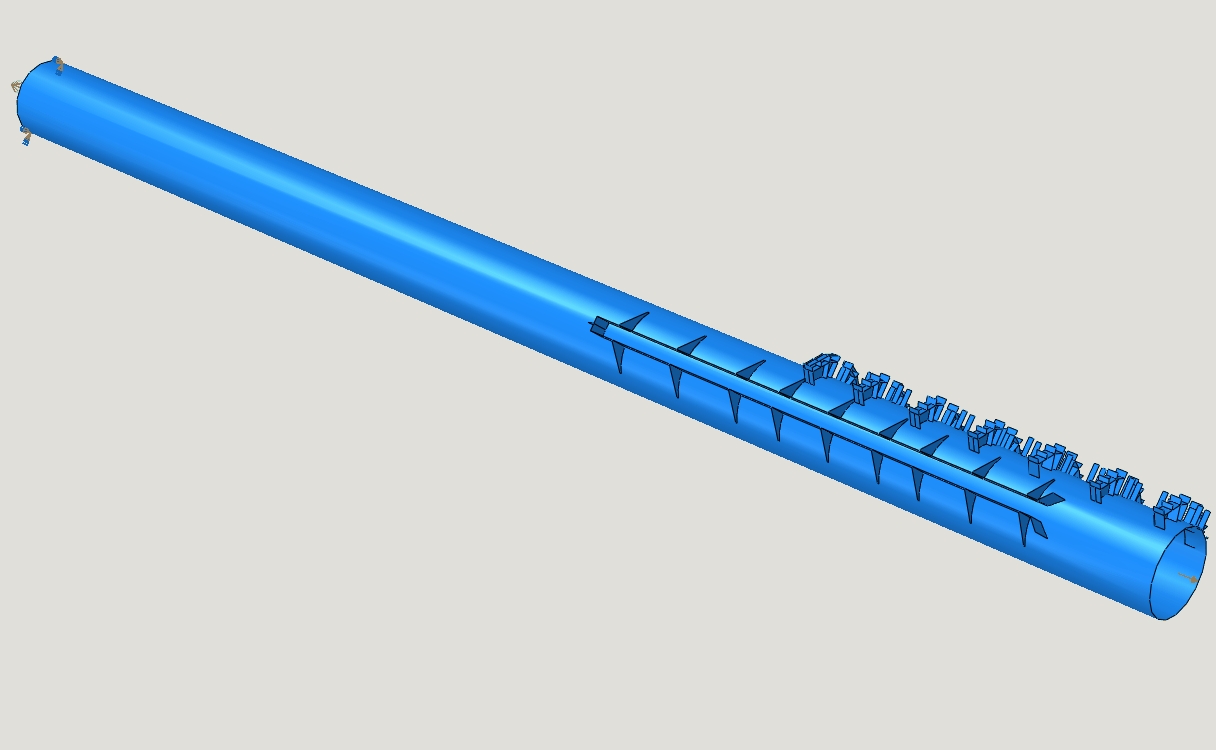
Shell model of the pile and its welded appendages
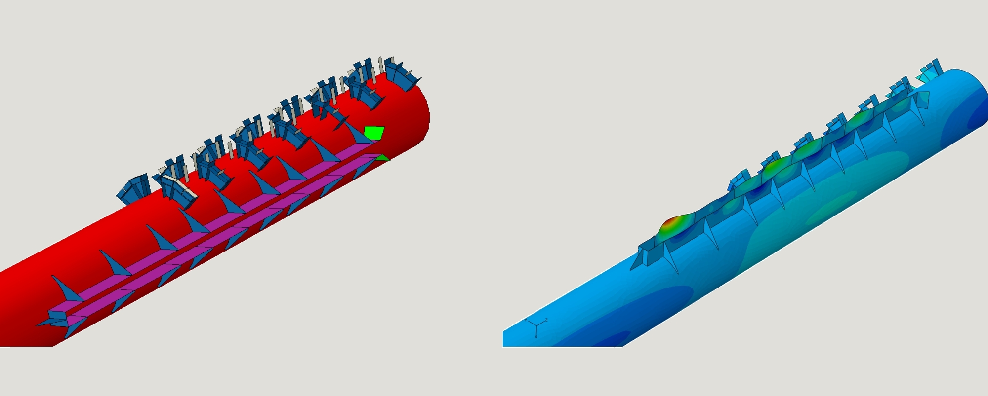
Detail of the welded appendages (left) and impression of the maximum deflections during piling
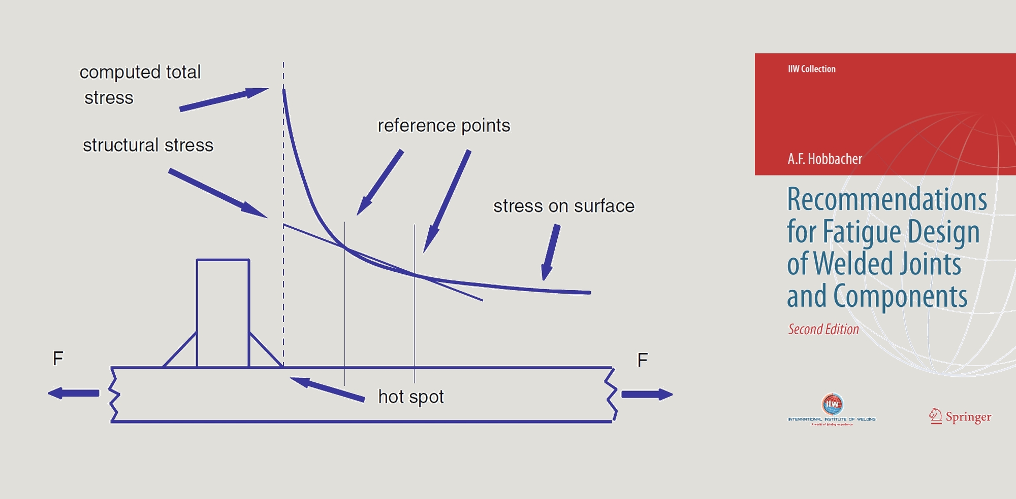
Extract from A. Hobbacher, Recommendations for Fatigue Design of Welded Joints and Components