temporary
fair stands
SCOPE
The structural verification of temporary fair stands may appear straightforward initially, but in practice, it can be more challenging for several reasons.
Firstly, these structures are typically constructed using custom aluminum profiles with non-standardized cross-sections. Most major producers have their own unique set of shapes for these profiles. Additionally, these profiles are often perforated to reduce weight and facilitate connections, infills, and fixings. Consequently, standardized libraries of stiffness and strength properties are not applicable, and these properties must be determined for each specific type of profile.
Secondly, due to the frequent assembly and disassembly of these stands, a variety of fasteners have been developed to speed up this process. These fasteners come in numerous shapes and operate on different principles. However, like the profiles, they lack standardization, necessitating the advance characterization of their behavior.
Lastly, these stands must bear not only their own weight, along with infills and additional fixings such as screens, but also lateral surface pressures. For instance, when constructing an indoor stand for an event at the Messe Essen, the exhibition stand construction regulations dictate that:
“Standing structural elements and/or special structures (e.g., free-standing walls, high exhibits, high decorative elements) that could tip over must be rated for at least a horizontally acting equivalent distributed load:
- 125 Pa up to a height of 4 m from the upper edge of the floor
- 63 Pa for all surfaces above a height of 4 m from the upper edge of the floor.”
This "wind" load can lead to significant bending stresses, which often play a dominant role in the design of these temporary stands.
APPROACH
This particular stand employs just two types of profiles and connectors, simplifying the process of characterizing their equivalent stiffness and strength properties. It's worth noting that more complex stands can incorporate dozens of profile and connector types. To determine these equivalent properties, detailed Finite Element models are utilized. In these models, the profiles and connectors are subjected to unit loads and moments, yielding correction factors for the profiles and equivalent translational and rotational stiffness for the connectors.
With this information in hand, a beam model of the stand is created in SCIA Engineer and analyzed according to Eurocode, specifically EN 1999-1-1. In this model, all components, including profiles and connectors, are represented as deformable beams with appropriate sections. The profiles are modeled without holes, and correction factors derived from the earlier step are applied to assess these profiles. Load panels are incorporated to simulate the paneling and account for the weight of the infills, as well as to define the wind load in four perpendicular directions. Additionally, concentrated loads are specified to consider the weights of screens and other attachments.
Lastly, both a sectional and buckling check are conducted to evaluate the structure, incorporating any necessary corrections as determined in the initial step. If required, modifications are made to the stand to ensure it complies with all the requirements of EN 1999-1-1.
RESULT
In the context of this specific project, it could be concluded that the structure can handle its load, as long as an additional wall measuring 0.5 meters by 3 meters was installed on the left side of the free-standing wall.
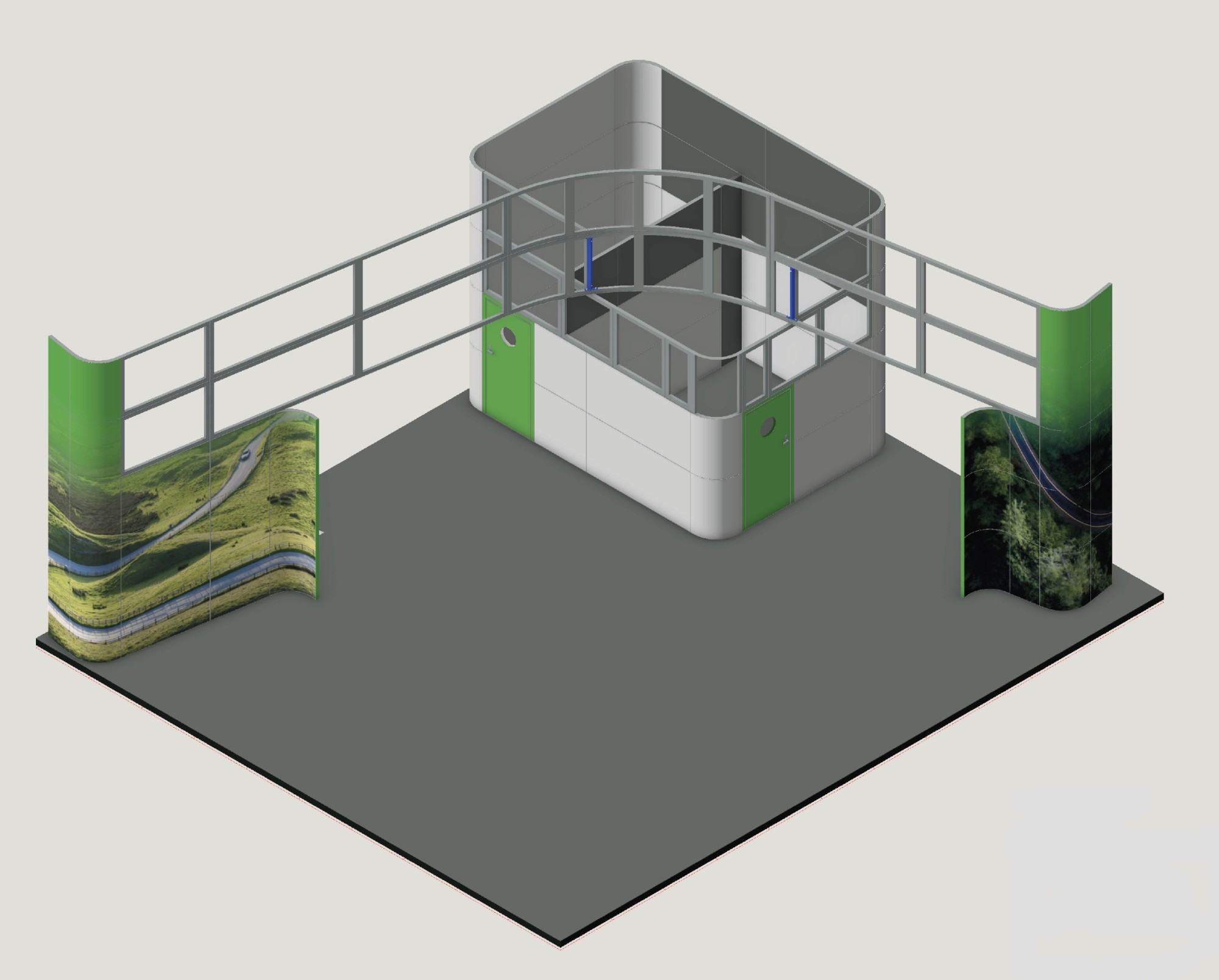
3D render of the main structure
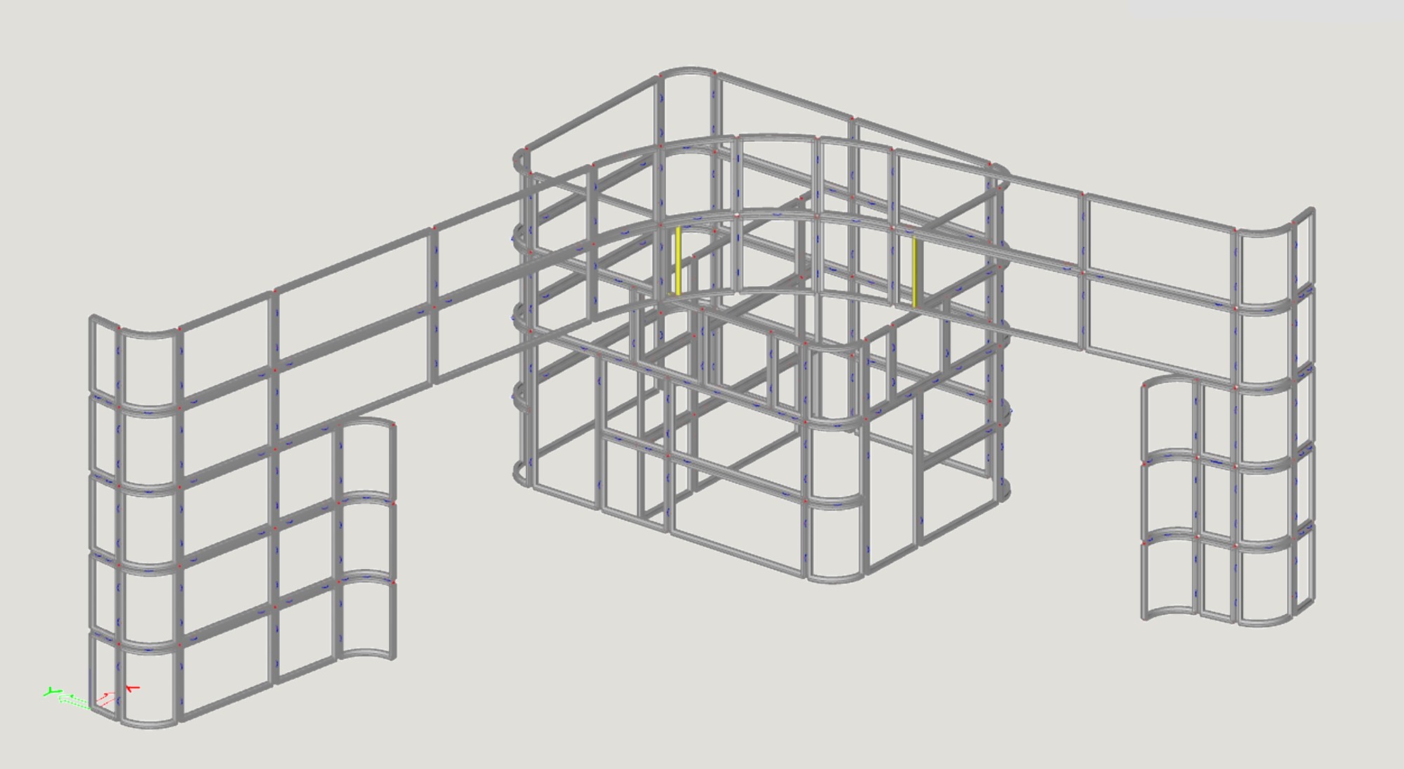
Beam model of the supporting structure
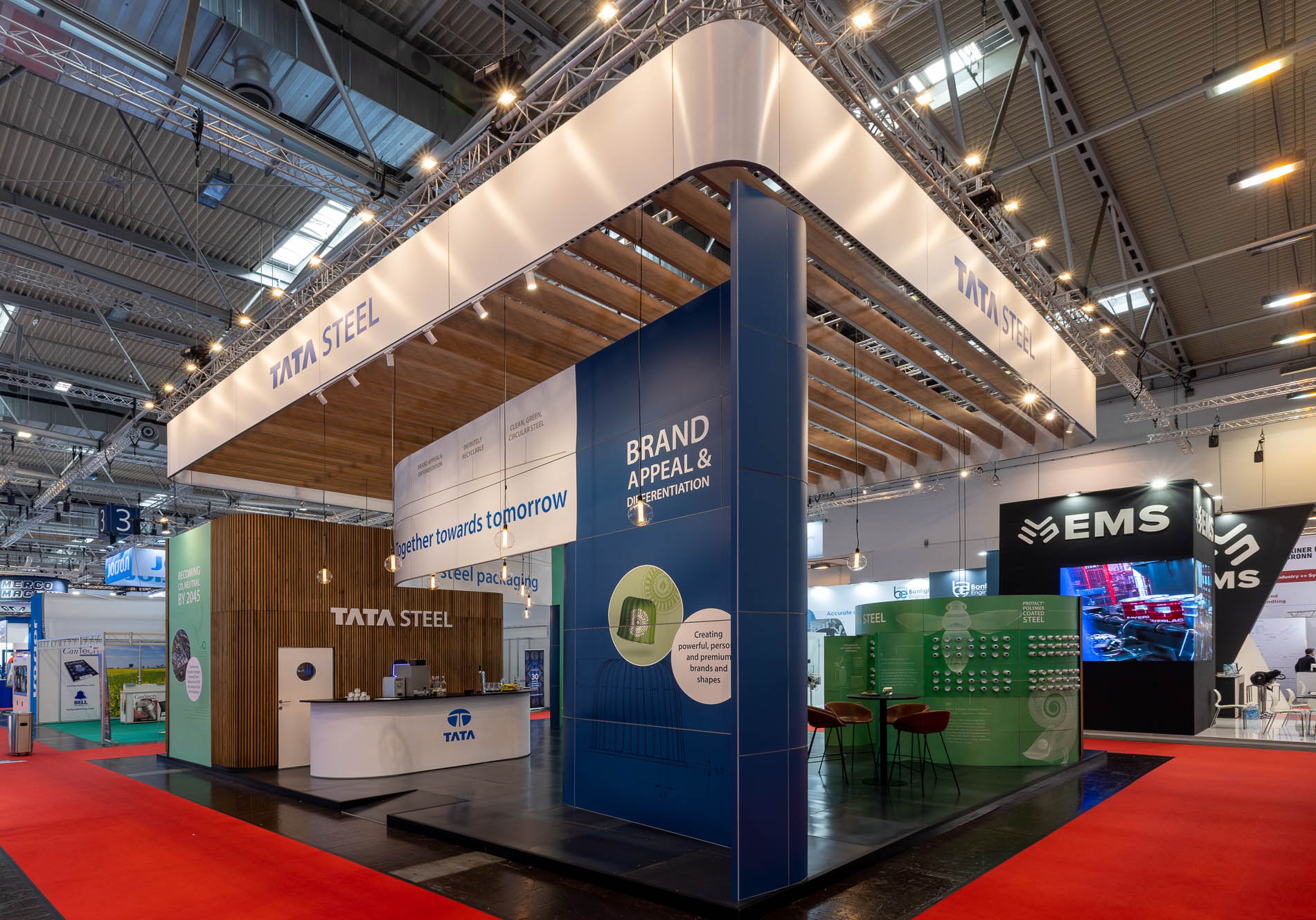
Fair stand as built for the Messe