giant
observation
wheel
SCOPE
This case involves the assessment of a large observation wheel produced by a European manufacturer. The steel structure's ability to resist static and fatigue loading was evaluated based on the EN 13814:2019 and ASTM F2291 design standards, which are the prevailing codes for amusement rides in Europe and the Americas, respectively. Additionally, the design was evaluated in accordance with Eurocodes and relevant EN codes for connection details and mechanical components.
This type of attraction comprises a static support structure and a rotating wheel. The wheel has an outer diameter of 56 meters and is mounted on a central axle positioned approximately 32 meters above ground level. Eight friction drive wheels, installed on the static support structure, apply pressure against the rim of the wheel to rotate it at a maximum speed of 1 rpm. The static support structure consists of two vertical A-frames that support the main axle, while two additional inclined support legs are hinged to the backside of the main axle. The observation wheel is divided into 20 sectors, each with 2 gondolas, making a total of 40 gondolas. Each gondola can accommodate up to 10 adult passengers, and the wheel can carry a maximum of 400 passengers at any given time. One of the notable design features of this observation wheel is the use of curved spokes, which enhance the overall aesthetic appeal of the attraction.
APPROACH
The design verification process for the observation wheel typically involves several phases. Firstly, wireframe models are used to evaluate the main components and standard connection details, taking into account all relevant loads and loading cases. These models are also used in the second phase to perform fatigue evaluations, with particular attention paid to the connections. The effect of many unbalanced load configurations is considered, as the distribution of passengers varies from one ride to another.
In the third phase, detailed shell and solid models are created in a general purpose FE software to verify local stresses at specific connection details. This is done for both static and fatigue load combinations, and fatigue evaluations are carried out using expert guideline procedures outlined in FKM, IIW and related documents.
In the fourth and final phase, multiple iterations are performed to assess the impact of design changes and arrive at a final design that meets all requirements of EN 13814 and other relevant standards. This phase also involves simulations to evaluate the erection and assembly of the observation wheel on site.
RESULT
The images on the right provide a glimpse of the observation wheel, which is presently under construction and slated to be installed in the next year or two.

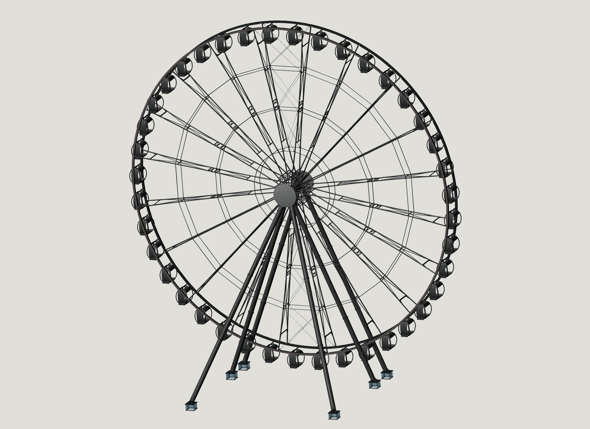
CAD model of the giant observation wheel
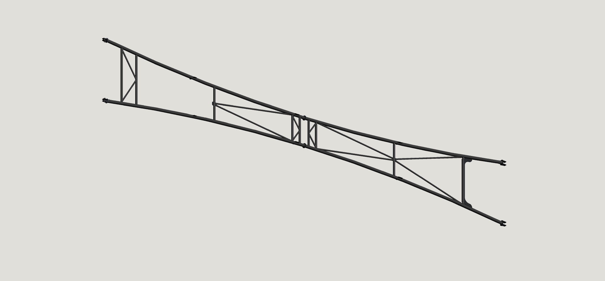
The curved spokes
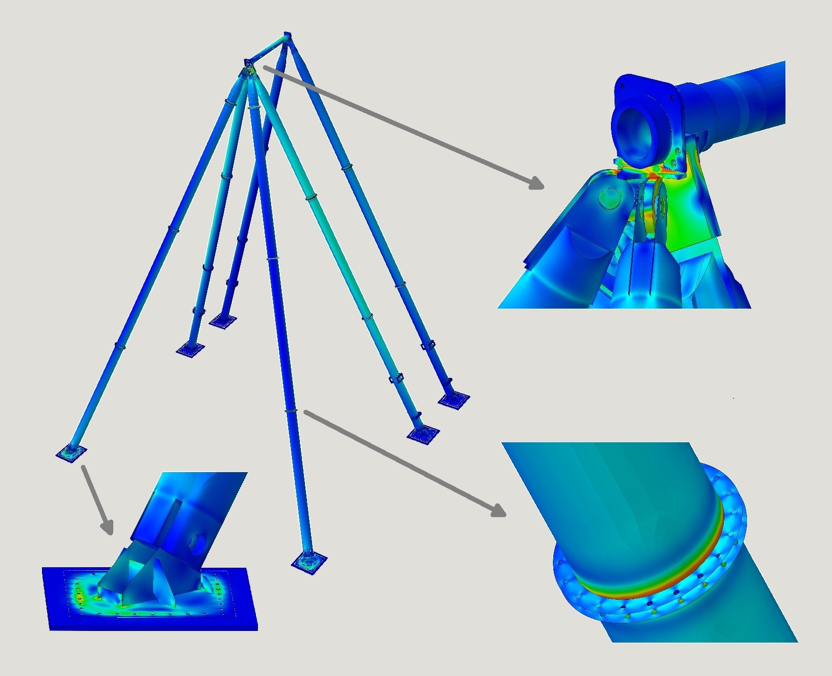
Example of an FE model of the supporting structure